Microtensile bond strength of CAD/CAM-fabricated polymer-ceramics to different adhesive resin cements
Article information
Abstract
Objectives
This study evaluated the microtensile bond strength (µTBS) of polymer-ceramic and indirect composite resin with 3 classes of resin cements.
Materials and Methods
Two computer-aided design/computer-aided manufacturing (CAD/CAM)-fabricated polymer-ceramics (Enamic [ENA; Vita] and Lava Ultimate [LAV; 3M ESPE]) and a laboratory indirect composite resin (Gradia [GRA; GC Corp.]) were equally divided into 6 groups (n = 18) with 3 classes of resin cements: Variolink N (VAR; Vivadent), RelyX U200 (RXU; 3M ESPE), and Panavia F2 (PAN; Kuraray). The μTBS values were compared between groups by 2-way analysis of variance and the post hoc Tamhane test (α = 0.05).
Results
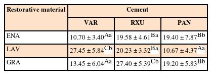
Restorative materials and resin cements significantly influenced µTBS (p < 0.05). In the GRA group, the highest μTBS was found with RXU (27.40 ± 5.39 N) and the lowest with VAR (13.54 ± 6.04 N) (p < 0.05). Similar trends were observed in the ENA group. In the LAV group, the highest μTBS was observed with VAR (27.45 ± 5.84 N) and the lowest with PAN (10.67 ± 4.37 N) (p < 0.05). PAN had comparable results to those of ENA and GRA, whereas the μTBS values were significantly lower with LAV (p = 0.001). The highest bond strength of RXU was found with GRA (27.40 ± 5.39 N, p = 0.001). PAN showed the lowest µTBS with LAV (10.67 ± 4.37 N; p < 0.001).
Conclusions
When applied according to the manufacturers' recommendations, the µTBS of polymer-ceramic CAD/CAM materials and indirect composites is influenced by the luting cements.
INTRODUCTION
Resin composites and ceramics are 2 major categories of esthetic materials that have been used for decades. These materials are constantly being further developed to overcome their weaknesses and to extend their indications [1]. It is believed that ceramics offer better mechanical and optical properties than their composite resin counterparts. However, ceramic materials are susceptible to fracture, and repair is problematic [2]. Compared to ceramics, composite resins cause less wear to the opposing dentition and intraoral repair is more convenient [34]. Applying heat and/or light to cured composite resins and reinforcing the microstructure led to a class of indirect composite resins with more desirable properties in clinical applications [5].
The use of computer-aided design/computer-aided manufacturing (CAD/CAM) technology can facilitate the fabrication of several types of restorations from prefabricated blocks made from a wide range of materials. Recently, a new category of CAD/CAM polymer-ceramic dental materials was introduced and was claimed to have more favorable mechanical properties than polymer or ceramic alone [16]. The ceramic and polymer phases of these materials are fabricated through different cutting-edge technologies. Resin nanoceramic (RNC), such as Lava Ultimate (LAV; 3M ESPE, St. Paul, MN, USA), consists of a highly cured resin matrix that is densely filled by nanoceramic particles (up to 80% by weight) and ceramic nanoclusters (Table 1). Polymer-infiltrated ceramic network (PICN), such as Enamic (ENA; Vita Zahnfabrik, Bad Sackingen, Germany), is a hybrid material containing interpenetrating dual-phase ceramic and composite [78].
With lower hardness and elastic modulus values than ceramics, but improved fracture toughness, these products exhibit more resistance to grinding-induced damage. Subsequently, rapid milling with less edge chipping could be expected [89]. The results of clinical studies of indirect composite restorations revealed that failure occurred mainly due to chipping, fracture, secondary caries, and debonding [1011]. Aside from the material microstructure and fabrication procedure, the success of bonding is affected by the cement type in combination with the bonding system and surface treatment. However, very few studies are available on the bond strength of resin cements to polymer-ceramic CAD/CAM [71213141516]. As polymer-ceramics are new products, practitioners are more likely to follow the manufacturers' instructions when using them.
Therefore, the aim of the present study was to investigate the microtensile bond strength (μTBS) of 3 resin cements and 2 polymer-ceramic restoratives and an indirect composite material after preparing and bonding according to the procedures recommended by the manufacturers. The null hypothesis tested was that neither the type of material nor the resin cement would influence the μTBS.
MATERIALS AND METHODS
This study sought to examine the µTBS of 3 restorative materials and 3 resin cements (Table 1).
CAD/CAM block preparation
One hundred and eight rectangular specimens (14 × 12 × 5 mm) were fabricated from CAD/CAM blocks of a PICN material (A2-LT/EM14, Enamic, Vita Zahnfabrik) and a RNC material (A2-LT/14L, Lava Ultimate, 3M ESPE) using a low-speed diamond saw (Isomet, Buehler, Lake Bluff, IL, USA). One surface of each specimen was wet-polished with 600-grit silicon carbide paper (Shanghai Abrasive Tools Co., Shanghai, China) for 30 seconds and cleaned in an ultrasonic cleaner (VU03H, Smeg Instruments, Guastalla, Italy) with distilled water.
Cementation procedure
The surface treatment of each group was performed according to the corresponding manufacturer's instructions.
In the ENA group, the bond surface was etched with 5% hydrofluoric (HF) acid (IPS Ceramic Etching Gel, Vivadent/Ivoclar, Schaan, Liechtenstein) for 60 seconds and rinsed thoroughly. Silane agent (Monobond N, Vivadent/Ivoclar) was applied and left until dried. For the LAV specimens, air-abrasion was performed with 50-µm aluminum oxide particles at a 1-mm distance under 0.2 MPa for 10 seconds. LAV specimens were cleaned in an ultrasonic cleaner (VU03H, Smeg Instruments) with 99% ethyl alcohol and dried.
For indirect composite resin specimens (DD2, GC Gradia [GRA], GC Corp., Tokyo, Japan), 54 specimens were fabricated using a split stainless-steel mold (5 × 5 × 5 mm). Composite resin was added incrementally in 1-mm thick layers and light-polymerized (Steplight SLI, GC Corp.) at 1,200 mW/cm2 and at a 10-mm distance for 20 seconds. The top-most layer was covered with a celluloid strip during light-polymerization to avoid formation of an oxygen inhibition layer. Finally, GRA specimens were light-polymerized in a specialized light chamber (Labolight, LVIII, GC Corp.) for 5 minutes and rinsed under running water for 60 seconds. The bond surface was air-abraded with 50-µm aluminum oxide particles at a 1-mm distance under 0.2 MPa for 10 seconds. Specimens were cleaned by 38% phosphoric acid (Total Etch, Vivadent/Ivoclar) for 15 seconds, rinsed under running water, and air-dried.
Specimens in each group were further divided into 3 groups (n = 18) by applying 3 different resin cements: dual polymerizing self-etch cement (Panavia F2 [PAN], Kuraray Noritake Dental Inc., Okayama, Japan), self-adhesive resin cement (RelyX U200 [RXU], 3M ESPE), and a dual-curing composite resin cement (Variolink N [VAR], Vivadent/Ivoclar). In total, 9 subgroups were tested. For each bonding procedure, 2 similar disks were bonded together, and the manufacturer's protocol was followed.
For RXU, 2 equal parts of each paste were automatically mixed and applied in thin layers to both bonding surfaces of each test group, and the layers were held together under a 500-gram weight for 60 seconds. Excess cement was removed by scalpel. Specimens were light-polymerized at 1,100 mW/cm2 (Bluephase, Vivadent/Ivoclar) for 20 seconds on each surface. For PAN, Clearfill porcelain activator (Kuraray Noritake Dental Inc.) and Clearfill bond primer (Kuraray Noritake Dental Inc.) were mixed, applied on both bond surfaces of the specimens, and air-dried. Equal parts of PAN paste were mixed, painted on the conditioned surfaces, and bonded for 35 seconds under a 500-gram weight. Excess cement was removed by scalpel. Specimens were light-polymerized at 1,100 mW/cm2 (Bluephase, Vivadent/Ivoclar) for 40 seconds on each surface. For VAR, 2 thin layers of Monobond N (Vivadent/Ivoclar) were applied to both bond surfaces of specimens and dried. Two pastes of VAR cements were auto-mixed, applied to both bond surfaces, and held together with the aid of a 500-gram weight. Excess cement was removed after light exposure for 2 seconds. Specimens were light-polymerized at 1,100 mW/cm2 for 30 seconds on each surface.
Thermo-cycling
The specimens were stored in water for 24 hours and then subjected to 3,000 thermal cycles between 5 and 55°C with a 30-second interval time.
Micro-tensile bond strength measurements
To obtain bars for the µTBS test, each bonded block was embedded in a clear acrylic mold (Acrosum, Betadent, Tehran, Iran), cut using a low-speed saw (Isomet, Buehler), and vertically sectioned into 1.5-mm-thick slices, which were further sectioned after 90° rotation. Bars were obtained from the center of the blocks; edges were not included in the test. Excluding lost specimens, 54 bars were prepared for each group of materials (n = 18). The µTBS bars were attached to a custom-made stainless steel jig made of two parts with a u-shaped notch in the middle. Specimens were placed in the notch, glued at both ends using a cyanoacrylate adhesive (Permabond gel, Permabond Engineering Adhesive Ltd., Hampshire, UK), and mounted on a universal testing machine (STM-20, Santam, Tehran, Iran). The fixation mechanism should ensure that a pure tensile force is applied to the specimen and that bending force during testing due to non-parallel loading is avoided. Tensile force was applied at a cross-head speed of 0.5 mm/min until fracture occurred. The µTBS was calculated in MPa by dividing the failure load (N) by the area (mm2). The cross-sectional area of each bar was measured with a digital caliper (Mitutoyo Inc., Kawasaki, Japan). Normal distribution of the data was verified through the Kolmogorov-Smirnov test. The mean values of µTBS tensile strength were statistically analyzed by 2-way analysis of variance (ANOVA) and the Tamhane post hoc test using SPSS ver 21.0 (SPSS Inc., Chicago, IL, USA) at the 95% significance level.
Failure mode analysis
Failure modes were examined on the fractured surfaces using a stereomicroscope (Nikon Metrology, Leuven, Belgium) with a magnification of ×50. The failure modes were classified as follows: type 1, adhesive failure (surface of the CAD/CAM material was visible); type 2, mixed failure in the CAD/CAM material and cement surfaces (resin cement was partially visible in certain areas); type 3, cohesive failure within the cement layer (almost all the fracture surface was covered with cement) [13].
Scanning electron microscope (SEM) observations
A representative sample of the untreated surfaces (as-block and after cutting) and a representative sample with a treated surface from each of the CAD/CAM groups were cleaned in an ultrasonic cleaner with isopropyl alcohol for 10 minutes, gold-sputtered to 20-nm thickness, and examined qualitatively using scanning electron microscopy (XL30E SEM, Philips, Omaha, NE, USA) at magnifications of ×2,500 and ×5,000.
RESULTS
Two-way ANOVA revealed that the type of restorative material and resin cement significantly affected µTBS, and their interaction was also significant (p < 0.05). Therefore, the effect of the cements varied according to the restorative material. Among the restorative materials, RXU and PAN achieved significantly higher bond strength than VAR, except for with LAV (Table 2). All GRA specimens fractured cohesively in the cement layer (type 3) while most failures in the other groups were type 2 fractures, with a lower percentage of type 3 fractures (Table 3).

Bond strength values in MPa and the results of multiple comparisons, according to the 2 variables of restorative material and cement type
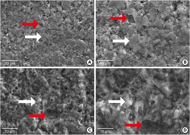
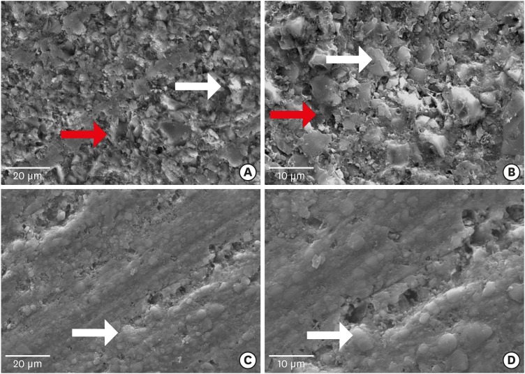
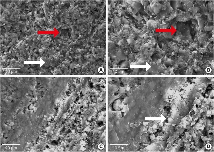
In the SEM observations of ENA blocks with no treatment, distinct and homogeneous ceramic and polymer phases with micropores of different sizes were observed (Figure 1A and 1B). Increased roughness and debris and/or smears were observed after cutting ENA blocks (Figure 2A and 2B). The HF-treated ENA specimens were more homogenous than the cut specimens (Figure 3A and 3B). The LAV block specimen was rougher than the ENA block specimen. Ceramic particles were uniformly intermingled with the polymer matrix, and distributed porosity was seen over the entire surface of the LAV block (Figure 1C and 1D). Decreased roughness and some round holes were observed after the LAV block was cut (Figure 2C and 2D). Sandblasting increased the surface roughness, porosity, and presence of round holes. In several areas, the polymer was separated from the surrounding ceramic particles (Figure 3C and 3D).

Scanning electron microscope images of computer-aided design/computer-aided manufacturing polymer ceramics before cutting. (A) Enamic (×2,500) showed a homogeneous distribution of the ceramic phase (white arrow) and the polymer phase (red arrow); (B) With higher magnification (×5,000), the ceramic particles with sharp edges (white arrow) and amorphous polymer phases (red arrow) were displayed; (C) LAVA Ultimate (×2,500) showed distributed roughness on the surface; (D) With higher magnification (×5,000), organic fibers (white arrow) embedded in the polymer matrix were observed.

Scanning electron microscope images of computer-aided design/computer-aided manufacturing polymer ceramics after cutting. (A) Enamic (×2,500); (B) With higher magnification (×5,000), more roughness than in the as-block specimen was seen (white arrow indicates ceramic particles and red arrow indicates polymer phase); (C) LAVA Ultimate (×2,500); (D) With higher magnification (×5,000), the cut surface of Lava Ultimate showed less roughness. More areas of porosity were distributed across the specimen than in the as-block specimen (whiter arrow indicates ceramic fiber).

Scanning electron microscope images of computer-aided design/computer-aided manufacturing polymer-ceramic after treatment. (A) Etched surface of Enamic (×2,500); (B) With higher magnification (×5,000), larger holes (white arrow) within a relatively unaffected polymer phase (red arrow) are seen; (C) Lava Ultimate after sand blasting (×2,500); (D) With higher magnification (×5,000), Lava Ultimate showed more roughness and porosity than untreated specimens. The cracks in the matrix could be seen (white arrow).
DISCUSSION
The results of the present study showed that cement type and restorative material significantly influenced the µTBS. Hence, the null hypothesis was rejected.
The µTBS of ENA/RXU and ENA/PAN was higher than that of ENA/VAR. The better performance of ENA/RXU and ENA/PAN could be explained by their mechanisms of adhesion to different substrates. ENA contains 86 wt% ceramics, of which 60 wt% is SiO2 and the rest is inorganic content [6]. The chemical reaction of RXU to ceramic-based materials occurs through the acid-base reaction of 2 phosphate groups in the acidic methacrylate monomer and hydroxyl groups in the ceramic surface and/or inorganic fillers [17]. Simultaneously, the radical polymerization of methacrylate monomers through their reactive carbon double bonds promotes copolymerization with another polymer material [18]. Moreover, RXU shows less shrinkage during setting than conventional resin cement that undergoes free-radical polymerization. Lower contraction stress results in lower interfacial stress, which is thought to be a source of failure in bonded surfaces [19]. An acidic functional monomer of 10-methacryloylloxydecyl hydrogen phosphate (10-MDP) in PAN plays a similar role to the phosphoric methacrylate monomer in RXU by bonding to ceramics and inorganic filler [7]. In addition, in the current study, SEM observations revealed that in the ENA specimens, roughness increased more homogenously after application of HF. As could be expected, the high ceramic content of ENA directed the surface treatment to selective dissolution of glassy content after exposure to HF, providing micromechanical retention for bonding. As confirmed by Campos et al. [20] and Elsaka [13], application of HF was the most effective method of enhancing bond strength to resin cements. Nevertheless, in the current study, using HF alone failed to create a strong bond to a dual-curing composite resin cement (i.e., VAR).
In the LAV group, the highest bond strength was achieved with VAR, followed by RXU and PAN. The highly polymerized matrix of LAV is filled with silica and zirconia nanoparticles and zirconia nanoclusters. Given the high bond strength of zirconia to MDP-containing adhesive, better bonding to PAN would have been anticipated [16]. This unexpected finding could be explained by the detrimental effect of sandblasting on the surface structure of Lava Ultimate. Yoshihara et al. [14] also reported that sandblasting of RNC blocks could damage the polymeric matrix, which is less hard than the fillers. SEM observations in the present study showed that despite the increasing surface roughness of LAV specimens, several disruptions appeared in the form of holes or cracks around the inorganic fillers (Figure 3D), which might cause debonding of the filler. Subsequently, it could be hypothesized that using Monobond N, which contains silane and phosphoric acid monomer, mediated bonding between the filler and polymeric matrix of VAR and LAV. As a result, any cracks induced by sandblasting would be sealed, resulting in better performance of VAR. In agreement with our study, Keul et al. [21] observed that the TBS of an experimental nanohybrid composite to VAR together with low-viscosity adhesive was higher than that of a phosphate ester-based self-adhesive cement (Clearfill SA). In contrast, Peumans et al. [15] found that the bond strengths of LAV and ENA improved after the application of air-abrasion and a silane agent. However, PAN performed better with LAV than with ENA, which contradicts our observations. This difference may be partly explained by the use of different surface treatments and test protocols.
In the GRA group, the bond strength was the highest with RXU and lowest with VAR. This result was somewhat unexpected because VAR is a dual-cured Bis-GMA resin cement that contains urethane dimethacrylate (UDMA) and triethylene glycol dimethacrylate (TEGDMA). Therefore, one might expect there to be copolymerization with a similarly composed composite resin base material (Table 1). However, GRA with a highly polymerized matrix provided very little residual monomer for bonding to resin cements. In addition, polymerized UDMA exhibits a highly cross-linked 3-dimensional structure that could trap free monomer molecules and make even less residual monomer available for further copolymerization [22]. Similar results were reported by Stawarczyk et al. [23]. Likewise, the dimethacrylate monomers in VAR are responsible for a highly cross-linked polymer structure after setting of the cement. This structure provides an insufficient active site for further copolymerization with another polymeric material, such as GRA composite [2425]. GRA showed the strongest bond with RXU, which may be attributed to the chemical reaction of cement with the inorganic filler in GRA, as discussed above. Consistent with our findings, Gilbert et al. [26] found that Unicem and Variolink 2 showed better bonding to a CAD/CAM composite than to 10-MDP–containing resin cement.
In the present study, most specimens exhibited mixed failure (type 2), although the GRA group showed mostly type 3 failure. Consistent with our observations, several authors found mixed failure in most of their specimens. The concentration of stresses at the corners of µTBS specimens, as confirmed by finite-element analysis [27], could be responsible for the mixed failure mode. However, the ‘true’ failure mode should be investigated by more accurate fractographic analysis.
Only the manufacturer-recommended surface treatment and bonding protocols were followed, but, based on our findings, it can be concluded that a universal bonding protocol may not be sufficient for achieving the strongest bond. For instance, air-abrasion of RNC (such as Lava Ultimate in the present study) may compromise its bonding with self-adhesive and self-etch resin cements. Evaluation of different surface treatments is recommended in future studies. The results of the present laboratory study cannot be used to predict clinical outcomes, although our findings may yield insights into the behaviors of the tested materials and their relative strength.
CONCLUSIONS
Within the limitations of this study, the bond strengths of 2 polymer-ceramic CAD/CAM materials and an indirect composite resin varied when treated following the manufacturers' pre-treatment protocols. Therefore, it may be concluded that the choice of resin cement can affect bond strength to polymer-ceramic and indirect composite resin, although the effect was material-dependent.
ACKNOWLEDGEMENT
The authors are grateful to Dr. Mohammad J Kharazi Fard for assistance with the statistical analysis, and the Nanoscale Biomedical Imaging Facility in the Hospital for Sick Children Research Institute and Mr. Doug Holmyard for assisting in the scanning electron microscope analysis. We express special thanks to Diba Teb Pars Co., for its generous provision of indirect composite materials.
Notes
Funding: This research was supported by a grant (No. #32381) from Tehran University of Medical Sciences.
Conflict of Interest: No potential conflict of interest relevant to this article was reported.
Author Contributions:
Conceptualization: Sadighpour L, Geramipanah F.
Data curation: Sadighpour L, Geramipanah F, Ghasri Z, Neshatian M.
Funding acquisition: Sadighpour L, Geramipanah F.
Investigation: Sadighpour L, Ghasri Z, Neshatian M.
Methodology: Sadighpour L, Geramipanah F, Ghasri Z, Neshatian M.
Project administration: Sadighpour L.
Resources: Sadighpour L.
Supervision: Sadighpour L, Geramipanah F.
Validation: Sadighpour L, Geramipanah F.
Visualization: Ghasri Z, Neshatian M.
Writing - original draft: Sadighpour L, Geramipanah F.
Writing - review & editing: Sadighpour L, Geramipanah F, Ghasri Z, Neshatian M.


