Comparative analysis of torsional and cyclic fatigue resistance of ProGlider, WaveOne Gold Glider, and TruNatomy Glider in simulated curved canal
Article information
Abstract
Objectives
This study aimed to compare the torsional and cyclic fatigue resistance of ProGlider (PG), WaveOne Gold Glider (WGG), and TruNatomy Glider (TNG).
Materials and Methods
A total of 15 instruments of each glide path system (n = 15) were used for each test. A custom-made device simulating an angle of 90° and a radius of 5 millimeters was used to assess cyclic fatigue resistance, with calculation of number of cycles to failure. Torsional fatigue resistance was assessed by maximum torque and angle of rotation. Fractured instruments were examined by scanning electron microscopy (SEM). Data were analyzed with Shapiro-Wilk and Kruskal-Wallis tests, and the significance level was set at 5%.
Results
The WGG group showed greater cyclic fatigue resistance than the PG and TNG groups (p < 0.05). In the torsional fatigue test, the TNG group showed a higher angle of rotation, followed by the PG and WGG groups (p < 0.05). The TNG group was superior to the PG group in torsional resistance (p < 0.05). SEM analysis revealed ductile morphology, typical of the 2 fracture modes: cyclic fatigue and torsional fatigue.
Conclusions
Reciprocating WGG instruments showed greater cyclic fatigue resistance, while TNG instruments were better in torsional fatigue resistance. The significance of these findings lies in the identification of the instruments’ clinical applicability to guide the choice of the most appropriate instrument and enable the clinician to provide a more predictable glide path preparation.
INTRODUCTION
A glide path is defined as a tunnel through which a small-caliber instrument travels along the entire length of the root canal, from the orifice to the physiological terminus, uninterruptedly. It is able to maintain the original canal anatomy, which minimizes the risk of fracture of preparation instruments [1]. The use of mechanical instruments to create a glide path has been associated with safer instrumentation. This is explained by the physical characteristics of such instruments, which favor the maintenance of the original canal anatomy compared with stainless-steel manual instruments [2].
The ProGlider (PG) nickel-titanium (NiTi) rotary file (Dentsply Sirona, Ballaigues, Switzerland) undergoes a thermal treatment known as M-wire. It has a square-shaped cross section, a 0.16-mm tip diameter, and a progressive taper ranging from 0.02 near the active portion to 0.08 near the shaft. Studies have shown greater torsional and cyclic fatigue resistance for this instrument compared with conventional NiTi glide path files [234]. The WaveOne Gold Glider (WGG) NiTi reciprocating file (Dentsply Sirona) undergoes a different thermal treatment, known as Gold. It has a parallelogram-shaped cross section, a 0.15-mm tip diameter, and a variable taper ranging from 0.02 to 0.06 [5]. Studies comparing the performance of WGG instruments with rotary glide path files found that the former had greater torsional and cyclic fatigue resistance [167].
Recently, TruNatomy (Dentsply Sirona), a rotary motion system featuring innovative taper, thermal treatment, and design [8], was introduced. One of the system instruments is the TNG, which is used to create a glide path. It has a centered parallelogram-shaped cross section, a 0.17-mm tip diameter, and an average taper of 0.02. Its active portion measures 14 mm and is designed with a variable regressive taper to ensure the end has a maximum diameter of 0.8 mm.
Because of the high flexibility of current canal shaping systems, glide path files are recommended for use in preparation, preferably mechanical ones. Thus, this study aimed to compare torsional and cyclic fatigue resistance of PG, WGG, and TNG files. The null hypotheses were that there would be no difference between the 3 glide path file systems in terms of both cyclic fatigue resistance and torsional fatigue resistance.
MATERIALS AND METHODS
A total of 15 instruments of each glide path system were used for each test, as established by sample size calculation. Sample size calculation was based on a 95% confidence level (type I error (α) = 5%) and an 80% power (type II error (β) = 20%). Based on these parameters, the minimum sample size for each group was estimated at 13 instruments. However, as a safety measure against possible losses, an additional 20% was used for each group. Before mechanical testing, all instruments were visually inspected under an operating microscope (Stemi 2000C, Carl Zeiss, Jena, Germany) at 16× magnification to identify possible defects or deformities. None were discarded [910]. In this study, the tests were conducted at a temperature of 20°C controlled by an air conditioner, thus standardizing the test environment.
Cyclic fatigue resistance
A custom-made device (Dabi Atlante S/A Indústrias Médico Odontológicas, Ribeirão Preto, SP, Brazil) was used to assess static cyclic fatigue resistance, consisting of an iron base (30 × 50 cm) with a fixing support for an electric motor. This support was held by brackets bolted to the iron base [1112]. After the instruments were coupled to the motor, angle and radius of curvature (90° and 5 millimeters, respectively), based on the Pruett method, were adjusted (Figure 1) [13].
All files were powered by a VDW Silver Reciproc electric motor (VDW, Munich, Germany) at a controllable torque, according to the manufacturer’s operating settings: PG (Dentsply Sirona) with rotary motion, speed of 300 rpm, and torque of 2 N/cm; WGG (Dentsply Sirona) with reciprocating motion, “WaveOne” mode; TNG (Dentsplay Sirona) with rotary motion, speed of 500 rpm, and torque of 1.5 N/cm. Glycerin was used as a lubricant during each test to minimize friction between the instrument and the device and to reduce heat generation and release [114].
Time to fracture was recorded with a digital stopwatch based on visual and auditory inspection. Number of cycles to failure (NCF) was calculated by multiplying rotational speed by time (in seconds) [1615]. Fragment length was measured with a digital microcaliper (Mitutoyo, Kawasaki, Japan) under a microscope at 16× magnification, to determine the distance from the instrument extremities to the point of fracture [14].
Torsional fatigue resistance
Before mechanical testing, all instruments were visually inspected under an operating microscope (Stemi 2000C, Carl Zeiss) at 16× magnification to identify possible defects or deformities. Any alterations detected in the instruments would be a reason for discarding them. None were discarded [910].
Torsional fatigue resistance was tested based on International Organization for Standardization 3630-1 with a torsion testing machine, as described elsewhere [9]. Before testing, the handle of each instrument was removed, and this end was fixed to the device. The other end, corresponding to the apical 3 millimeters of the instrument, was clamped to a mandrel to prevent sliding. With the piece immobilized, torque was applied evenly until fracture occurred. To avoid biases regarding the influence of cyclic fatigue, the instrument was placed straight, i.e., with no curvature [1016]. The reciprocating instrument (WGG, Dentsply Sirona) was rotated counterclockwise, with a rotational speed of 2 rpm, while the rotary instruments (PG, Dentsply Sirona; TNG, Dentsplay Sirona) were rotated clockwise, with the same speed [101516]. Torque values \\xe2\\x80\\x8b\\xe2\\x80\\x8b(N/cm) were measured by the force exerted on a small load cell by a lever arm linked to the torsion axis. Measurement and control of angle of rotation (0°) were performed by a resistive transducer linked to a process controller [11]. All data were collected with software (MicroTorque, Analógica, Belo Horizonte, MG, Brazil).
Scanning electron microscopy (SEM) analysis
After the cyclic fatigue test, fractured instruments were examined with a scanning electron microscope (Phenom ProX, ThermoFisher Scientific, Waltham, MA, USA) for analysis and description of fracture characteristics, such as location of initial cracks and fatigue/overload zones [4515]. Similarly, after the torsional fatigue test, fractured files were assessed with the same microscope, but this time to observe the topographic characteristics of fractured surfaces. Prior to this analysis, the files were cleaned in an ultrasonic cleaning device to eliminate debris [910].
Statistical analysis
Data were analyzed with descriptive and inferential statistics in IBM SPSS (version 25.0, IBM Corporation, Armonk, NY, USA). First, Shapiro-Wilk normality test showed that all variables were normally distributed (p > 0.05). Then, Levene test and 1-way analysis of variance with post hoc Tukey honestly significant difference test were performed. For all analyses, the significance level was set at 5%.
RESULTS
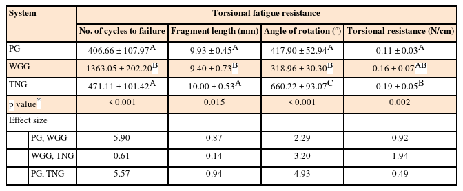
Means and standard deviations of torsional and cyclic fatigue resistance for each instrument group are shown in Table 1. The WGG group had higher NCF values, which indicates higher cyclic fatigue resistance (1,363.05 ± 202.20), differing statistically from the PG (406.66 ± 107.97) and TNG (471.11 ± 101.42) groups (p < 0.05). The PG and TNG groups did not differ statistically from each other (p > 0.05).

Torsional and cyclic fatigue resistance of different endodontic glide path instruments (n = 15 per system)
Regarding time to fracture, higher values were found for the WGG group (233.66 ± 34.66), followed by the PG (81.33 ± 21.59) and TNG (56.53 ± 12.17) groups (p < 0.05). Fracture length was smaller for the WGG group (9.40 ± 0.73) (p < 0.05), while the PG (9.93 ± 0.45) and TNG (10.00 ± 0.53) groups did not differ statistically from each other (p > 0.05).
In the torsional fatigue test, the TNG group had a higher angle of rotation (660.22 ± 93.07), followed by the PG (417.90 ± 52.94) and WGG (318.96 ± 30.30) groups (p < 0.05). For torsional resistance (N/cm), the TNG group (0.19 ± 0.05) was superior to the PG group (0.11 ± 0.03) (p < 0.05). The WGG group showed similar behavior to the other systems (p > 0.05).
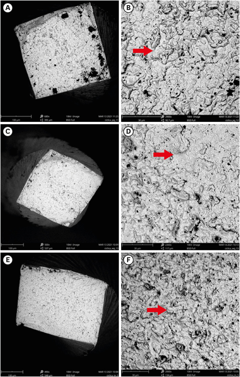
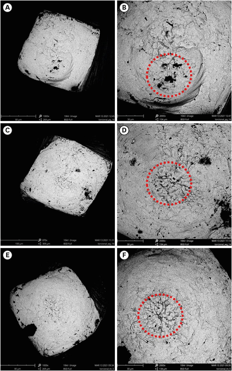
SEM analysis revealed ductile morphology, typical of the 2 fracture modes: cyclic fatigue and torsional fatigue. The samples fractured by cyclic fatigue showed microcavities with grooves/ridges of multiple shapes across the entire surface of the cross section (Figure 2). There were also fatigue striations and initial cracks, in addition to fatigue/overload zones. The samples used in the torsional fatigue test showed microvoids and concentric abrasion marks, with skewed dimples near the center of the section (Figure 3).

Representative scanning electron microscopy images (cross-sectional aspects) of the fractured surfaces of the ProGlider (A, B), WaveOne Gold Glider (C, D), and TruNatomy Glider (E, F) instruments after the cyclic fatigue test. The red arrows indicate typical features of this type of fracture, such as ductile dimples. (A, C, E) ×500 magnification; (B, D, F) ×3,000 magnification.

Representative scanning electron microscopy images (cross-sectional aspects) of the fractured surfaces of the ProGlider (A, B), WaveOne Gold Glider (C, D), and TruNatomy Glider (E, F) instruments after the torsional fatigue test. Within the red dotted circles, skewed dimples in the center of the section are typical of this type of fracture. (A, C, E) ×500 magnification; (B, D, F) ×3,000 magnification.
DISCUSSION
Creating a glide path is important to reduce the stress to which canal preparation instruments are subjected, as this free tunnel minimizes operative errors such as instrument fracture and canal deviation. Instrument fracture is caused by torsional and cyclic fatigue, which was the focus of this study [15].
Mechanical fatigue testing may increase the temperature of the instrument, inducing a decreased resistance to cyclic fatigue [2]. In this study, the tests were conducted at a temperature of 20°C controlled by an air conditioner, thus standardizing the test environment. Further studies are needed to evaluate the cyclic fatigue resistance of different NiTi instruments at different temperatures.
Three different files (PG, WGG, and TNG) for creating a glide path were examined in this study. Despite their small size, they all have different physical characteristics in terms of tip diameter and taper. While PG and WGG files have a progressive taper along the active portion, TNG files have a variable regressive taper. For the creation of a glide path, previous studies have shown the influence of different physical characteristics of an instrument, such as tip diameter, taper, kinematics, thermal treatment, and design [6141517181920].
The results of this study showed that the WGG group had higher cyclic fatigue resistance (indicated by NCF and time to fracture) than the PG and TNG groups, which did not differ from each other. Also, the PG and TNG groups showed similar fragment lengths, which were longer than that of the WGG group. Therefore, the first null hypothesis was rejected.
Several studies have compared cyclic fatigue resistance of PG and WGG files, but, to the best of our knowledge, none has made a comparison with TNG files. Serefoglu et al. [6] assessed PG and WGG files using an artificial canal with an angle of curvature of 90º (the same angle used in the present study) and a radius of curvature of 3 mm (while this study used a radius of 5 mm), and found greater cyclic fatigue resistance in WGG files, which is consistent with the present results. Keskin et al. [5] and Kırıcı and Kuştarcı [7] also reported that WGG files were superior to PG files.
The better results for WGG files in the cyclic fatigue test can be attributed to 2 combined factors: the reciprocating motion of the file and the Gold thermal treatment it undergoes [21]. The reciprocating motion releases instrument stress as it performs 3 counterclockwise and clockwise cycles to complete one turn (360°) and thus reduces the risk of cyclic fatigue due to tension and compression [22]. Conversely, poorer cyclic fatigue results for PG and TNG files may be associated with rotary motion, and this type of motion already consists of a greater number of rotational cycles generated by the file. However, because they have a small taper, glide path instruments reach the foramen rapidly and, thus, do not remain for a long time inside the canal. Therefore, NCF in this study probably exceeded the number usually observed under clinical conditions, suggesting that PG and TNG files also provide safe clinical use in terms of cyclic fatigue.
Torsional fatigue resistance was assessed in this study because, given their small taper, glide path files show greater fragility compared with shaping files, which may favor rupture when the instrument tip becomes locked in the canal. The results showed that the TNG group had higher angles of rotation, followed by the PG and WGG groups. Torsional resistance was also higher in the TNG group, but differences were significant only in relation to the PG group. The WGG group showed similar results in relation to the others. Therefore, the second null hypothesis was also rejected.
The better results for angle of rotation in the TNG group and the equivalent results for torsional resistance in the TNG and WGG groups can be explained by the post-machining thermal treatment used for both instruments, which, according to the manufacturer, contributes to greater resistance. In addition, the Gold thermal treatment provides the instruments with a greater amount of stable martensite compared with the M-wire treatment, thus making the alloy more ductile and flexible [23]. This may explain why WGG instruments (which undergo the Gold treatment) were superior to PG instruments (which undergo the M-wire treatment) in terms of torsional fatigue resistance. The TruNatomy system undergoes a new thermal treatment that, despite not being fully known, possibly follows the current trend towards a predominance of martensite phase. However, more studies are needed to confirm this finding.
Based on SEM images of fractured instruments after the torsional fatigue test, the TNG group, which initially had a parallelogram-shaped cross section, became more square-shaped. The higher values \\xe2\\x80\\x8b\\xe2\\x80\\x8bfor angle of rotation and torsional resistance in the TNG group may be associated with greater instrument distortion, which contributed to the interpretation of the results.
The better performance for the TNG group regarding angular deflection (angle of rotation) is related to the ability of an instrument to undergo plastic and elastic deformation prior to fracture [24]. Thus, this deformation is a safety factor for clinical use [2526]. Having good torsional resistance properties is essential for instruments designed to create a glide path [102627].
The mechanical properties of the instruments may be related to design differences in cross section, taper, and tip diameter [162728]. In this study, although instruments designed exclusively for creating a glide path with similar physical characteristics were used, there are known differences between them that may impact fatigue test results. One example is that the TNG file has a variable taper throughout its active portion, while the PG and WGG files have a constant taper in the apical 3 millimeters. This makes it difficult to measure the cross-sectional area at D3, the point at which the instrument was fixed in the test and where torsional fracture occurs. D3 was chosen because it is indicated as the most likely site of instrument fracture [272829]. Previous papers stipulated area measurements at D3, but, to the best of our knowledge, there are no reports of area measurements for the TruNatomy system at this site [2728].
In endodontic practice, WGG and TNG glide path files appear to be more resistant to torsional fatigue than PG files and, therefore, are safer options for use prior to canal shaping. The TruNatomy shaping files prioritize dentin preservation, especially the pericervical region, and, therefore, TNG files should be indicated for use with this system.
CONCLUSIONS
Within the limitations of the present study, reciprocating WGG instruments showed greater cyclic fatigue resistance while TNG instruments were better in torsional fatigue resistance. Such mechanical properties have a major influence on the choice of instrument to create a glide path.
Notes
Conflict of Interest: No potential conflict of interest relevant to this article was reported.
Author Contributions:
Conceptualization: Kato AS, Vivan RR.
Data curation: Calefi PHS.
Formal analysis: Bueno CES.
Methodology: Vivan RR.
Project administration: Duarte MAH.
Writing - original draft: Dias PS.
Writing - review &editing: Pelegrine RA.


